Crack spacing of reinforced concrete
Concrete is a brittle material and can only withstand small amount of tensile strain due to stress before cracking. When a reinforced concrete member is put in tension, after cracking, the member elongates by widening of cracks and by formation of new cracks.

Ignoring the small elastic strain in the concrete between the cracks, we can relate the crack width to the strain of the member by:
Spacing of primary cracks
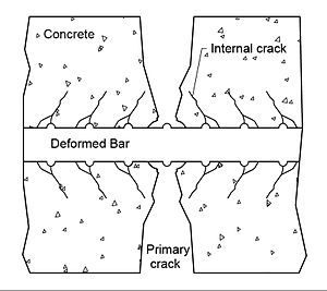
Primary cracks (Figure 1) form when the tensile stress at the outer surface of the concrete reaches the tensile strength of concrete. When a primary crack forms, the concrete in the vicinity of the crack is relieved of any tension, resulting in a stress free zone near the crack.[1]
CEB-FIP code expressions for crack spacing and crack widths
In the CEB-FIP Code the following expression is used to account for the average crack spacing:
where
- = clear concrete cover
- = maximum spacing between longitudinal reinforcing bars (shall not be taken greater than )
- = bar diameter
- =
- = area of steel considered to be effectively bonded to the concrete
- = area of effective embedment zone of the concrete where the reinforcing bars can influence the crack widths. The effective embedment zone is the area of concrete around the reinforcing bar at the distance of 7.5 bar diameter
- = coefficient that characterizes bond properties of bars
- = 0.4 for deformed bars
- = 0.8 for plain bars
= coefficient to account for strain gradient
- (e1 and e2 = the largest and the smallest tensile strains in the effective embedment zone)
Crack spacing of inclined cracks
According to the Modified Compression Field Theory (MCFT), the spacing of inclined cracks in reinforced concrete will depend upon the crack control characteristics of both the longitudinal and the transverse reinforcement. It is suggested that the spacing is taken as:
Where is the average crack spacings that would result if the member was subjected to longitudinal tension while is the average crack spacing that would result if the member was subjected to a transverse tension.[2]
These crack spacings can be estimated from the CEB-FIP Code crack spacing expression above.
Crack spacing in shear areas
The above CEB expression was intended to calculate crack spacings on the surface of the member. Crack spacings become larger as the distance from the reinforcement increases. For this case, it is suggested to use the maximum distance from the reinforcement, instead of cover distance c (Collins & Mitchell). Thus, for the uniform tensile straining the above CEB expression is modified to:
The above equations are suggested for better approximation of crack spacings in the shear area of the beam.
References
- ^ Piyasena, Ratnamudigedara (2003). Crack Spacing, Crack Width, and Tension Stiffening Effect in Reinforced Concrete Beams and One-way Slabs. Griffith University.
- ^ griffith.edu.au. "Crack Spacing, Crack Width and Tension Stiffening Effect in Reinforced Concrete Beams and One-Way Slabs" (PDF). griffith.edu.au. Archived (PDF) from the original on 2020-07-17.
- Collins & Mitchell (1997). Prestressed Concrete Structures. Canada: Response Publications. pp. 152, 349. ISBN 978-0968195802.
- CEP-FIP (1978). Model Code for Concrete Structures: CEP-FIP International Recommendations. Paris: Comite Euro-International du Beton. p. 348.


