Turn and slip indicator

In aviation, the turn and slip indicator (T/S, a.k.a. turn indicator and turn and bank indicator) and the turn coordinator (TC) variant are essentially two aircraft flight instruments in one device. One indicates the rate of turn, or the rate of change in the aircraft's heading; the other part indicates whether the aircraft is in coordinated flight, showing the slip or skid of the turn. The slip indicator is actually an inclinometer that at rest displays the angle of the aircraft's transverse axis with respect to horizontal, and in motion displays this angle as modified by the acceleration of the aircraft.[1] The most commonly used units are degrees per second (deg/s) or minutes per turn (min/tr).[citation needed]
Name
The turn and slip indicator can be referred to as the turn and bank indicator, although the instrument does not respond directly to bank angle. Neither does the turn coordinator, but it does respond to roll rate, which enables it to respond more quickly to the start of a turn.[2]
Operation

Turn indicator
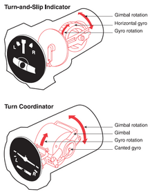
The turn indicator is a gyroscopic instrument that works on the principle of precession. The gyro is mounted in a gimbal. The gyro's rotational axis is in-line with the lateral (pitch) axis of the aircraft, while the gimbal has limited freedom around the longitudinal (roll) axis of the aircraft.
As the aircraft yaws, a torque force is applied to the gyro around the vertical axis, due to aircraft yaw, which causes gyro precession around the roll axis. The gyro spins on an axis that is 90 degrees relative to the direction of the applied yaw torque force. The gyro and gimbal rotate (around the roll axis) with limited freedom against a calibrated spring.
The torque force against the spring reaches an equilibrium and the angle that the gimbal and gyro become positioned is directly connected to the display needle, thereby indicating the rate of turn.[3] In the turn coordinator, the gyro is canted 30 degrees from the horizontal so it responds to roll as well as yaw.
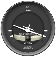
The display contains hash marks for the pilot's reference during a turn. When the needle is lined up with a hash mark, the aircraft is performing a "standard rate turn" which is defined as three degrees per second, known in some countries as "rate one". This translates to two minutes per 360 degrees of turn (a complete circle). Indicators are marked as to their sensitivity,[4] with "2 min turn" for those whose hash marks correspond to a standard rate or two-minute turn, and "4 min turn" for those, used in faster aircraft, that show a half standard rate or four-minute turn. The supersonic Concorde jet aircraft and many military jets are examples of aircraft that use 4 min. turn indicators. The hash marks are sometimes called "dog houses", because of their distinct shape on various makes of turn indicators. Under instrument flight rules, using these figures allows a pilot to perform timed turns in order to conform with the required air traffic patterns. For a change of heading of 90 degrees, a turn lasting 30 seconds would be required to perform a standard rate or "rate one" turn.
Inclinometer
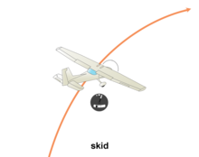
Coordinated flight indication is obtained by using an inclinometer, which is recognized as the "ball in a tube". An inclinometer contains a ball sealed inside a curved glass tube, which also contains a liquid to act as a damping medium. The original form of the indicator is in effect a spirit level with the tube curved in the opposite direction and a bubble standing in for the ball.[5] In some early aircraft the indicator was merely a pendulum with a dashpot for damping. The ball gives an indication of whether the aircraft is slipping, skidding or in coordinated flight. The ball's movement is caused by the force of gravity and the aircraft's centripetal acceleration. When the ball is centered in the middle of the tube, the aircraft is said to be in coordinated flight. If the ball is on the inside (wing down side) of a turn, the aircraft is slipping. And finally, when the ball is on the outside (wing up side) of the turn, the aircraft is skidding.
A simple alternative to the balance indicator used on gliders is a yaw string, which allows the pilot to simply view the string's movements as rudimentary indication of aircraft balance.
Turn coordinator

The turn coordinator (TC) is a further development of the turn and slip indicator (T/S) with the major difference being the display and the axis upon which the gimbal is mounted. The display is that of a miniature airplane as seen from behind. This looks similar to that of an attitude indicator..[6] "NO PITCH INFORMATION" is usually written on the instrument to avoid confusion regarding the aircraft's pitch, which can be obtained from the attitude indicator.
In contrast to the T/S, the TC's gimbal is pitched up 30 degrees from the transverse axis. This causes the instrument to respond to roll as well as yaw[6] and allows the instrument to display a change more quickly as it will react to the change in roll before the aircraft has even begun to yaw. Although this instrument reacts to changes in the aircraft's roll, it does not display the roll attitude.
The turn coordinator may be used as a performance instrument when the attitude indicator has failed. This is called "partial panel" operations. It can be unnecessarily difficult or even impossible if the pilot does not understand that the instrument is showing roll rates as well as turn rates. The usefulness is also impaired if the internal dashpot is worn out. In the latter case, the instrument is underdamped and in turbulence will indicate large full-scale deflections to the left and right, all of which are actually roll rate responses.
Practical implications


Slipping and skidding within a turn is sometimes referred to as a sloppy turn, due to the perceptive discomfort it can cause to the pilot and passengers. When the aircraft is in a balanced turn (ball is centered), passengers experience gravity directly in line with their seat (force perpendicular to seat). With a well balanced turn, passengers may not even realize the aircraft is turning unless they are viewing objects outside the aircraft.
While aircraft slipping and skidding are often undesired in a usual turn that maintains altitude, slipping of the aircraft can be used for practical purposes. Intentionally putting an aircraft into a slip is used as a forward slip and a sideslip. These slips are performed by applying opposite inputs of the aileron and rudder controls. A forward slip allows a pilot to quickly drop altitude without gaining unnecessary speed, while a sideslip is one method utilized to perform a crosswind landing.
Current Legal Status
Although the Turn and Slip Indicator (and later the Turn Coordinator) was felt to be a necessary and required instrument for flight under instrument flight rules, the Federal Aviation Administration (FAA) has more recently decided that these instruments are obsolete in today's flight environment. Advisory Circular No. 91-75, issued on 6/25/2003, states the following: [section 5 b] "...in today's air traffic control system, there is little need for precisely measured standard rate turns or timed turns based on standard rate." The Advisory Circular further states: "...the FAA believes, and all other commenters apparently agree...the rate-of-turn indicator is no longer as useful as an instrument which gives both horizontal and vertical attitude information." Thus one can now legally replace a Turn-and-Slip or Turn Coordinator instrument with a second attitude indicator, preferably driven by a system different from the primary flight display. So if the aircraft primary display is vacuum powered, the second attitude indicator should be electric, and vice-versa. This gives more flight information than the rate-of-turn indicator and gives a safety measure of redundancy of systems. The slip indicator (the "ball") is still required. The slip indicator may be mounted separately in the panel, or, some attitude indicators now have a slip indicator included in the display.
See also
References
- Advisory Circular AC 61-23C, Pilot's Handbook of Aeronautical Knowledge, U.S. Federal Aviation Administration, Revised 1997.
- Advisory Circular AC 91-75, Issued June 25th, 2003
- FAA-H-8083-15 Instrument Flying Handbook, U.S. Federal Aviation Administration (IFH), (Update 25 Nov 05)
- Operation demonstration of a Turn & slip indicator. The indicator cover is removed and gyro is displayed as it operates.
- ^ "Archived copy" (PDF). Archived from the original (PDF) on 2014-02-11. Retrieved 2014-02-28.
{{cite web}}: CS1 maint: archived copy as title (link) - ^ "Archived copy" (PDF). Archived (PDF) from the original on 2015-09-24. Retrieved 2015-02-05.
{{cite web}}: CS1 maint: archived copy as title (link) - ^ "How Aircraft Instruments Work." Popular Science, March 1944, pp. 117.
- ^ "MS28041 H SHEET INDICATOR TURN SLIP 28V DC 1-7/8 INCH". Archived from the original on 2015-11-20.
- ^ A. C. Kermode (2006). Mechanics of Flight. Pitman Boots LTD. p. 243. ISBN 978-1-4058-2359-3.
- ^ a b "Chapter 5. Flight Instruments". Instrument Flying Handbook (PDF) (FAA-H-8083-15B ed.). Federal Aviation Administration Flight Standards Service. 2012. p. 21.
