Phase-fired controller

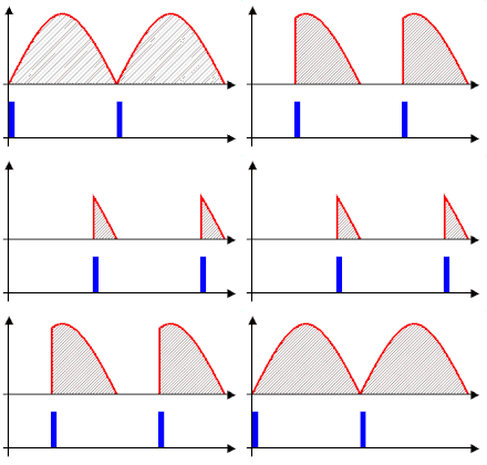
Phase-fired control (PFC), also called phase cutting or phase-angle control, is a method for power limiting, applied to AC voltages.[1] It works by modulating a thyristor, SCR, triac, thyratron, or other such gated diode-like devices into and out of conduction at a predetermined phase angle of the applied waveform.[2]
Overview
Phase-fired control (PFC) is often used to control the amount of voltage, current or power that a power supply feeds to its load. It does this to create an average value at its output. If the supply has a DC output, its time base is of no importance in deciding when to pulse the supply on or off, as the value that will be pulsed on and off is continuous.
PFC differs from pulse-width modulation (PWM) in that it addresses supplies that output a modulated waveform, such as the sinusoidal AC waveform that the national grid outputs. Here, it becomes important for the supply to pulse on and off at the correct position in the modulation cycle for a known value to be achieved; for example, the controller could turn on at the peak of a waveform or at its base if the cycle's time base were not taken into consideration.
Phase-fired controllers take their name from the fact that they trigger a pulse of output at a certain phase of the input's modulation cycle. In essence, a PFC is a controller that can synchronise itself with the modulation present at the input.
Most phase-fired controllers use thyristors or other solid-state switching devices as their control elements. Thyristor-based controllers may use gate turn-off (GTO) thyristors, allowing the controller to not only decide when to switch the output on but when to turn it off, rather than having to wait for the waveform to return to the next zero crossing.
Output reduction by bucking
A phase-fired controller, like a buck-topology switched-mode power supply, is only able to deliver an output voltage not exceeding its input, minus any losses occurring in the control elements themselves. Provided the modulation during each cycle is predictable or repetitive, as it is on the national grid's AC mains, to obtain an output lower than its input, a phase-fired control simply switches off for a given phase angle of the input's modulation cycle. By triggering the device into conduction at a phase angle greater than 0 degrees, a point after the modulation cycle starts, a fraction of the total energy within each cycle is present at the output.
"Boosting" by derating
To achieve a "boost"-like effect, the PFC designs must be derated such that the maximum present at the input is higher than the nominal output requirements. When the supply is first turned on or operating under nominal conditions, the controller will continually be delivering less than 100% of its input. When a boost is required, the controller delivers a percentage closer to 100% of the maximum input available.
Derating of mains-powered phase-fired controllers is important as they are often used to control resistive loads, such as heating elements. Over time, the resistance of heating elements can increase. To account for this, a phase-fired control must be able to provide some degree of extra voltage to draw the same heating current through the element. The only way of achieving this is to purposely design the supply to require less than 100% of the input's modulation cycle when the elements are first put in place, progressively opening the supply up towards delivering 100% of the input modulation cycle as the elements age.
Applications
The most common application is in dimmer switches for domestic lighting control.
For industrial applications previously, extremely expensive and heavy multi-tapped transformers were used as the supplies for such elements, with the corresponding winding tap being connected to the element to produce the desired temperature. This limited the temperature resolution to the number of tap combinations available. They often find their way into controllers designed for equipment such as electric ovens and furnaces.
In modern, usually high-power, equipment, the transformer is replaced with phase-fired controllers connecting the load directly to the mains, resulting in a substantially cheaper and lighter system. However, the method is usually limited to use in equipment that would be unrealistic without it. This is because the removal of the mains transformer means that the load has electrical continuity with the input. For industrial ovens and furnaces the input is often the national grid AC, which is itself electrically referenced to ground. With the controller's output referenced to ground, a user need only be in contact with earth and one of the output terminals to risk receiving an electrical shock. With many high-power items of equipment running from three-phase 415 V[clarification needed], high-current inputs and having any enclosure or framework present earthed (grounded), this is a serious risk that must be carefully assessed.
History
The first patent for phase-fired controllers derives from 1912.[citation needed] However, realization was first possible in the 1920s, when mercury-arc valve rectifiers with control grids became available. Because of the limitations of mercury-arc valves this method of voltage regulation was not common at the time. It became widespread with the invention of solid-state thyristors at the end of the 1950s.
See also
References
- ^ Software and hardware applications of microcomputers. M. H. Hamza, G. K. F. Lee, IEEE Control Systems Society, International Society for Mini-Microcomputers. Anaheim, Calif.: ACTA Press. 1986. p. 2. ISBN 0-88986-085-8. OCLC 24541232.
{{cite book}}: CS1 maint: others (link) - ^ D.W., McDonald (1980). "ac power control in the Core Flow Test Loop".
{{cite journal}}: Cite journal requires|journal=(help)
