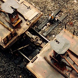
Janney coupler
| Part of a series on |
| Rail transport |
|---|
 |
| Infrastructure |
|
|
| Service and rolling stock |
|
| Urban rail transit |
|
|
| Miscellanea |
|
|
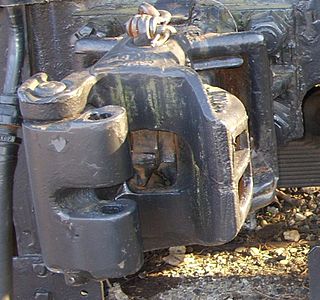
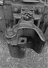
Knuckle couplers are a semi-automatic form of railway coupling that allow rail cars and locomotives to be securely linked together without rail workers having to get between the vehicles.
Originally known as Janney couplers (the original patent name) they are almost always referred to as Knuckles in the US and Canada (regardless of their actual official model name, nowadays generally various AAR types in North America), but are also known as American, AAR, APT, ARA, MCB, Buckeye, tightlock (in the UK) or Centre Buffer Couplers.
There are many variations of knuckle coupler in use today, and even more from the past, some variants of knuckle include:
Janney: the American original, a rather finicky coupler; reportedly annoying to make open and close.
Castle: an improvement on the Janney design, and a step towards the modern knuckle.
Split Knuckle: a rarer type, which replaces the finger of the Knuckle (the little flap that actually links two knuckles together, one of the few moving parts) with one that has a cut out in the middle of it and a hole bored through it; this modification was designed to work with the older Link and Pin couplers in widespread use before, though could reasonably work with European style chain couplers too.
AAR: AAR, the modern American knuckle, they have several variants of their own; ranging from the standard knuckle, to long drawbar ones, to passenger models, to a type designed specifically for tank cars.
Background

Janney couplers were first patented in 1873 by Eli H. Janney (U.S. patent 138,405).[2][3] Andrew Jackson Beard was amongst various inventors that made a multitude of improvements to the knuckle coupler;[1] Beard's patents were U.S. patent 594,059 granted 23 November 1897, which then sold for approximately $50,000, and U.S. patent 624,901 granted 16 May 1899.
In the UK, several versions of Janney couplers are fitted to a limited number of coaches, multiple units, wagons and locomotives.
Janney Type E, Type F Interlock, and Type H tightlock couplings are compatible subtypes, each intended for specific rail car types.
Prior to the formation of the Association of American Railroads (AAR) these were known as Master Car Builder (MCB) couplers.[4] In 1934, the MCB was renamed as the AAR.
Knuckle couplers of the 1880s and 1890s had a chaotic mixture of proprietary internal components, but all had the standard MCB external contour, making them compatible. There was a multitude of makes and models — Burns, Climax, Gould, Miller, Sharon and Tower. Some worked better than others.
In 1913, American Steel Foundries (ASF) developed the Janney "Type D" coupler, that was then made the MCB standard coupler for North America; new and rebuilt rolling stock had to be fitted with that coupler. That ended the market for knuckle couplers with proprietary components, excepting those exported from the US to other countries not complying with MCB standards.
The Alliance coupler, named after the ASF-owned foundry in Alliance, Ohio, was developed as a lighter build than the "Type D", and was marketed by the Amsted Corporation, parent of ASF, as the "Standard for the World". It is still the most-used knuckle coupler in the world. The modern Alliance coupler still uses the modern AAR-10 or 10A contour, but has a shorter thus weaker head length, and thus cannot be used on North American interchanged rolling stock.
Manufacturers of modern "Type E", "Type F Interlock" and "Type H Tightlock" couplers include McConway & Torley,[5][6] ASF, and Buckeye, also known as Columbus Castings.
The external contour of Janney knuckle couplers was the first aspect to be standardized by the MCB in the 1880s. Prior to this, there was a chaotic variety of constantly evolving and proprietary external contours and internal components. In 1893, manufacturers standardized on the MCB-5 or Type C contour, then in 1915 on the improved MCB-10 or Type D contour, and again in 1932 on the AAR-10A or Type E contour. The 1893, 1915, and 1932 contours are measurably different with slight dimensional changes that improved performance, yet remain compatible. Janney couplers still use the 1932 contour, though tolerances, metallurgy and machining techniques have improved, resulting in notable reductions in coupler slack. Type H tightlock couplings used on passenger stock have a variation of the 10A contour that nearly eliminates slack during normal operation and minimizes the possibility of "telescoping" during a derailment.
Purpose
The purpose of couplers is to join rail cars and locomotives to each other so they all are securely linked together. Major Eli Janney, a Confederate veteran of the American Civil War, invented the semi-automatic knuckle coupler in 1868. It automatically locks the couplers on cars or locomotives together without a rail worker having to get between the cars, and replaced the link and pin coupler, which was a major cause of railroad worker injuries and deaths. The locking pin that ensures Janney couplers remain fastened together is withdrawn manually by a worker using the "cut lever", which is operated from either side of the railroad car and does not require the person to go between the cars. The only time the worker has to go between cars is after they have been securely coupled, to hook up the air lines for the pneumatic brakes, and the head-end power cables in the case of passenger cars.
Modern Janney couplers typically mount to rail cars and locomotives via draw gear; early Janney couplers often had transitional shanks which mounted into legacy link and pin coupler pockets, or bolted directly to steam locomotive headstocks.
Janney/MCB/ARA/AAR/APTA coupler
Knuckle couplers are used in the Americas, Africa, Asia-Pacific, UK, Belgium and Spain (narrow gauge railway only).
Among its features:
- Maximum tonnage as high as 32,000 metric tons (35,000 short tons; 31,000 long tons) such as on the Fortescue Railway.[citation needed]
- Minimum ultimate tensile strength:
- Grade E knuckles: 650,000 pounds-force (2.9 MN)[7]
- Grade C or Grade E knuckles are required [8] for interchange service.
- Grade E coupler bodies: 900,000 pounds-force (4.0 MN)[7]
- Grade E knuckles: 650,000 pounds-force (2.9 MN)[7]
- Several knuckle coupler types exist to accommodate various cars, but all are required to have certain common dimensions allowing for compatibility.[9]
- Lighter weight railways, notably narrow-gauge lines with no need for interchange, sometimes use smaller (three-quarter- or half-size) versions of the Janney MCB coupler.[10] Such as Victorian narrow gauge lines.
- Janney couplers are always right-handed, i.e., their shape resembles the human right hand with fingers curled, as viewed from above.
- Required coupler heights, in North America[8]
- Empty cars: 33.5 inches (851 mm) ± 1 inch (25 mm)
- Loaded cars: 32.5 inches (826 mm) ± 1 inch (25 mm)
- Modern AAR standards require knuckle couplers to be bottom-operated on cars and top-operated on locomotives.[11] Operation or uncoupling is accomplished by lifting the release pin with a lever extending to the corner of the car; this pin is locked when the coupler is under tension, so the usual uncoupling steps are to compress the coupling with a locomotive, lift and hold up the pin, then pull the cars apart. "Buckeye" [12] and "SASKop" couplers are side operated variants of knuckle couplers.
- Trains fitted with knuckle couplers can accommodate heavier loads than any other type of coupler.[citation needed]
- In North America, knuckle couplers are typical per AAR and APT standards; mainline freight trains often exceed 1 mile (1.6 km) long; in Europe[citation needed] freight trains are typically much shorter, with the legacy buffers and chain coupler remaining the de facto standard.
- In New Zealand, heavy coal trains were first fitted with knuckle couplers in 1972; a full transition began in 2013 to replace remaining Norwegian couplers with knuckle couplers on freight stock and Scharfenberg couplers on passenger stock.
Janney Type E
Janney Type E double-shelf couplers are yet another variety, typical on North American hazardous material tank cars. [13][14][15] The Janney coupler is commonly used on railway couplings, as it is strong and locks automatically. Janney coupler was patented by Eli Janney after the US Civil War. The Janney interlocking coupling system is much safer than the links before it. Janney coupler is like two curved human hand.[16][17]
Gooseneck coupler
With gooseneck couplers or offset shank couplers, the horizontal centerline of the coupler head is above the horizontal centerline of the coupler shank, or shaft, and the draw gear. This arrangement is designed for use with low-floor freight cars, to lift the coupler head high enough to match the couplers on other rolling stock.[18] The large bogie boxvans for car parts, used on the Victorian Railways, were fitted with gooseneck couplers for that reason.
Henricot coupler
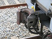
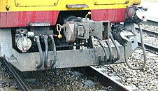
The Henricot coupler, a variation on the Janney coupler, was introduced by Belgian engineer and entrepreneur Émile Henricot of Court-Saint-Étienne. It is used on certain electric multiple units of the Belgian State Railways, including the NMBS/SNCB class 75.
 |
|
|
||||
| A Trainset 174 of the National Railway Company of Belgium | Henricot Type D coupler on a Belgian EMU | Close-up of Henricot coupler and separate air brake and head-end power connections on a NMBS/SNCB class 75 |
Development of the knuckle coupler
Janney was a dry goods clerk and former Confederate Army officer from Alexandria, Virginia, who used his lunch hours to whittle from wood an alternative to the link and pin coupler. The term Buckeye comes from the nickname of the US state of Ohio, the "Buckeye state" and the Ohio Brass Company[19] which originally marketed the coupling.[12][20]
In 1893, satisfied that an automatic coupler could meet the demands of commercial railroad operations and, at the same time, be manipulated safely, the US Congress passed the Safety Appliance Act. Its success in promoting switch-yard safety was stunning. Between 1877 and 1887, approximately 38% of all railworker accidents involved coupling. That percentage fell as the railroads began to replace link and pin couplers with automatic couplers. By 1902, only two years after the SAA's effective date, coupling accidents constituted only 4% of all employee accidents. Coupler-related accidents dropped from 11,710 in 1893 to 2,256 in 1902, even though the number of railroad employees steadily increased during that decade.[21]
When the Janney coupling was chosen to be the American standard, there were 8,000 patented alternatives to choose from. The only significant disadvantage of using the AAR (Janney) design is that sometimes the drawheads need to be manually aligned.
During the transition period from link-and-pin couplers, knuckle couplers on many locomotives had a horizontal gap and a vertical hole in the knuckle itself to accommodate, respectively, a link and a pin, to enable it to couple to vehicles which were still equipped with the older link-and-pin couplers.
- History
- Janney Coupler
Sketch From 1873 Patent - Syracuse Malleable Iron Works – 1894. MCB5 Transition Coupler, compatible with link and pin coupling
- MCB Type 5 coupler circa 1893. Split knuckle accommodates link and pin coupler or Johnston coupler. Vertical hole in knuckle accommodates the pin. Could also have accommodated a buffers and chain coupler with an extra pin.
Changes since 1873

The knuckle coupler has withstood the test of time since its invention, with only minor changes:[10]
- The current AAR contour dates back to the 1888 Master Car Builders Association (MCBA) design, which, in turn is based on the 1879 Janney patent.[4]
- Buckeye coupler, a side-operated version of the MCBA coupler[12]
- Type D coupler, adopted in 1916 by the MCBA (predecessor of ARA), had individual parts interchangeable, simplifying maintenance. Earlier designs had compatible profiles, but component parts differed between manufacturers, creating maintenance problems when cars were interchanged with other railroads.
- Type E coupler, adopted in 1930 by the ARA (predecessor of AAR), also had individual parts interchangeable, though not with Type D due to improvements. Still the most widely used design today.[22] Tank cars carrying hazardous materials are equipped with Type E double shelf couplers.[23][24][25][26]
- Type F coupler, a vertically interlocking variation to prevent accidents, derailments and wrecks from disconnecting the coupler. Type F also includes versions with rotating shafts for hopper car rotary dumpers, such as on the Pilbara railways and Transnet Freight Rail's Sishen-Sandanha Iron Ore and Ermelo-Richards Bay Coal Terminal lines.
- Type H coupler, a "tight-lock" variation to reduce slack action and improve safety for passenger cars. Now under the supervision of the APTA (American Public Transportation Association).
- Improvements in metallurgy and casting techniques to increase maximum trailing load.
- Some narrow-gauge railways such as the Victorian Puffing Billy Railway use a three-quarter-[10] or one-half-scale version of the Janney/MCB coupler.
Bazeley Coupler
Bazeley Coupler 1905-1918 M.C.B. D Type established as the Universal M.C.B. Standard, Adopted 1915
Arthur James Bazeley (1872-1937), railway couplings inventor/design engineer; was born in Bristol, England, in 1872, and worked for the Great Western Railway until the age of 34 when he immigrated to Cleveland, Ohio, in 1906, where he worked as a mechanical engineer for National Malleable Castings, Co., inventing and designing improvements in the function, strength, and durability of the (MCB/ARA/AAR/APTA) Janney, Knuckle, Alliance couplers and other coupling devices/draw gear for the evolving heavier demands by US railways, as well as, National Malleable Castings' international customers in the United Kingdom, India, and many other countries building and expanding their railway systems. A.J. Bazeley was directly responsible for over 90 registered U.S. patents for railway automatic coupler improvements through design, under the coupler type names which included the "Buckeye coupler", the "Sharon Coupler" PAT APP Nov. 10, 1910, 1911,1913, 1914, the "Simplex Coupler" PAT APP May 3, 1903, the "Climax Coupler", the "Latrobe Coupler", the "Tower Coupler", the "Major Coupler", the "Gould Coupler", the "Pitt Coupler", the "R.E. Janney Coupler", the "Kelso Coupler" and others.
A.J. Bazeley related railway inventions, U.S. patents and railway coupler mechanical drawings and illustrations filed and assigned to National Malleable Castings Company can be referenced by a patent search under "Bazeley, railway couplings" or "Arthur James Bazeley, railway couplings patents" which have been drawn/filed and provided by Roger Bazeley-USA, MSTM, MSID, CHSRM Mineta Transportation Institute, Transportation Industrial Designer. A.J. Bazeley Railway Coupling, Construction/Design Improvements and Draft Rigging related patents include: US 1193222, US 124622, US 1932719, US 1518299, US 1932503, US 2235194, US 1932440 and others.
National Malleable Castings in 1891 absorbed the Chicago Malleable Iron which was founded in 1873 by Alfred A. Pope and John C. Coonley, who operated similar companies in Ohio and Indiana. By the late 1880s, the company employed nearly 1,000 men at its 26th and Western Chicago works, which manufactured various railroad couplers and steel products for the railroad industries. In 1891, Chicago Malleable became part of the new National Malleable Castings Co., the Cleveland-based company, where Arthur J. Bazeley was employed as a senior design engineer, had additional manufacturing plants across the Midwest. National Malleable purchased the Latrobe Steel & Coupler's plant in Melrose Park, Illinois, in 1909. In 1923, when it had begun to supply the automobile industry, the company changed its name to National Malleable & Steel Castings. Its stock was listed on the New York Stock Exchange beginning in 1936 [27]
The National Malleable Castings Bazeley Coupler 1905-1918 M.C.B. D Type as Universal M.C.B. Standard Adopted 1915
At a joint M.C.B. Coupler Committee meeting on July 15, 1913, out of numerous studied competing railway coupler manufacturers and designs two couplers were selected for the new proposed universal U.S./Canadian coupler design standard, adopted, June 15, 1916 by the M.C.B. The two couplers accepted were the Malleable Castings Company Bazeley Coupler, and the American Steel Foundries No.3 modified Alliance Coupler, out of nine couplers submitted to the committee as embodying the joint specification of design, The TYPE D coupler design based on The National Malleable Castings Bazeley Coupler patented designs and improvements was selected as the standard M.C.B Association's standard from 1918., after M.C.B. performance tested it along with the Type C designs.
The Type “D” Experimental Standard M.C.B. Coupler was unanimously recommended by the Master Car Builders Association and its Coupler Committee for adoption as the National/International (United States/Canadian) standard for coupler design and manufacturing specification uniformity by the M.C.B. Master Car Builders’ Association on June 15, 1916 after its 1915 Convention. This resulted in the sharing of U.S. Patent improvements and agreed to by The National Malleable Castings Company, Henry Pope President; The Buckeye Steel Castings Company, The Gould Coupler Company, American Steel Foundries and The Monarch Steel Castings Company, and to be the active standard M.C.B. D Type forward from January 1, 1918. Buckeye Steel Castings Company was founded in 1881 as the Murray-Hayden Foundry before changing to The Buckeye Automatic Car Coupler Company and in 2002 after filing bankruptcy was reformed as Columbus Castings.
Railway couplers were manufactured in accordance with the Standard Specifications of the AAR covering the purchase and acceptance of couplers, knuckles, locks and other working parts as shown in their "Mechanical Division Manual of Standards and Recommended Practice". Specifications as of March 1939 required that the fabrication casting material be of open hearth or electric furnace grade "B" steel with specific metallurgic requirements to insure proper tensile strength and reliability of the coupler and its moving parts. In order to govern uniform standards for the interchangeability and the proper relation between fitting parts, the A.R.A. Committee on Couplers and draft gears designed and distributed templates, gauges, and master guides to assure the proper interchangeability and fitting of parts to maintain the proper operation of various multi-source manufactured railway couplers.[28]
Gallery
- Janney couplers
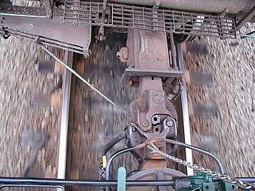
- Mated Janney Type E couplers, as seen from above. Left is top-operated on locomotives. Right is bottom-operated on cars
- AAR Type E coupler with top operator on mobile crane.
- "Drophead" coupler swung down reveals buffers and chain coupler on a British Rail Class 91.
- AAR Type E couplers. Upper is bottom operated on car. Lower is top operated on locomotive
- AAR Type E coupler (left) c. 1932, MCB Type 5 coupler (right) required by 1893 Railroad Safety Appliance Act.
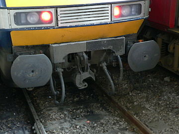
- AAR Type H coupler on British Rail Class 321 with full auto power and control connections.
- Two AAR Type E couplers
- Type E double-shelf coupler on a tank car. The double shelf holds the pair of couplers in place in a derailment, which reduces the chance of the coupler puncturing the tank.
- Two type E Janney couplers
See also
- Buckeye Steel Castings
- Draft gear
- Drawbar (haulage)
- Dual coupling
- Gangway connection
- Headstock (rolling stock)
- Jane's World Railways, lists the coupler(s) used on any railway system
- Railway coupling
- Railway coupling by country
- SA3 coupler
- Slack action
- South Station (Boston), includes a sculpture built of railroad car couplers
- Three-point hitch
- Tightlock coupling
References
- ^ a b US patent 594059
- ^ Eli Janney — The Janney Coupler
- ^ Inventors: Eli Janney - The Janney Coupler. Railroad Car Couplers / About, Inc
- ^ a b MCB
- ^ "McConway & Torley". Archived from the original on 2015-03-15. Retrieved 2014-07-07.
- ^ McConway & Torley
- ^ a b AAR Manual of Standards and Recommended Practices, Section S, Part I:Casting Details, Issue 06/2007
- ^ a b AAR 2011 Field Manual
- ^ AAR Manual of Standards and Recommended Practices, Section S, Part III: Coupler and Yoke Details, Issue 06/2007
- ^ a b c "NATIONAL MODEL RAILROAD ASSOCIATION DATA SHEET" (PDF). Archived from the original (PDF) on 2013-08-20. Retrieved 2013-11-15.
- ^ "Bottom operated". Archived from the original on 2011-12-13. Retrieved 2013-05-22.
- ^ a b c Buckeye coupler (scroll down)[dead link] Archived September 26, 2006, at the Wayback Machine
- ^ Type E double shelf
- ^ "Columbus Castings Couplers and Yokes". Archived from the original on 2013-05-30. Retrieved 2013-05-26.
- ^ "Archived copy" (PDF). Archived from the original (PDF) on 2014-03-10. Retrieved 2013-05-26.
{{cite web}}: CS1 maint: archived copy as title (link) - ^ "Knuckle Couplers". RMI Railworks.
- ^ "The Janney coupler - ASME". www.asme.org.
- ^ Offset or gooseneck couplers
- ^ Ohio Brass Company
- ^ Ohio Brass company
- ^ Clark, Charles H. (1972). "The Development of the Semiautomatic Freight-Car Coupler, 1863-1893". Technology and Culture. 13 (2): 207. doi:10.2307/3102610. ISSN 0040-165X.
- ^ "Link and Pin Couplers".
- ^ "Type E and Type F couplers". Archived from the original on 2013-05-30. Retrieved 2013-05-26.
- ^ "Safety and research" (PDF). Archived from the original (PDF) on 2014-03-10. Retrieved 2013-05-26.
- ^ Tedrail
- ^ "Double Shelf Couplers Tank Cars - Bing images".
- ^ Wilson, Mark R. "Electronic Encyclopedia of Chicago". www.encyclopedia.chicagohistory.org. Retrieved 30 June 2014.
- ^ The A.R.A. STANDARD Type "E" COUPLER March 1931, page 9


